Prerequisites
Account Required
Make sure you have created an account on the platform before starting the hardware setup process.
-
ParticularMatter Account Create a free account at dashboard.particularmatter.org
-
USB Cable & Computer Micro-USB cable and a computer with a modern web browser (Chrome, Edge, or Opera with WebUSB support)
-
WiFi Network 2.4 GHz WiFi network (ESP32 does not support 5 GHz networks)
-
Basic Tools (for hardware assembly) Soldering iron (optional), screwdrivers, wire strippers if assembling from scratch
Hardware Assembly
Build your own air quality sensor or purchase a pre-assembled unit. The total cost for DIY components is approximately €142–173 depending on optional components.
Shopping List
| Component | Price |
|---|---|
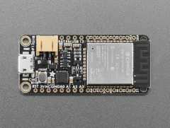 Adafruit HUZZAH32 – ESP32 Feather Board
|
~€20 |
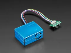 PM2.5 Air Quality Sensor Kit (PMS5003)
|
~€35 |
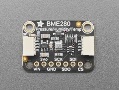 Adafruit BME280 Temperature / Humidity / Pressure Sensor
|
~€13 |
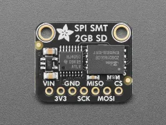 Adafruit SPI Flash SD Card (XTSD 2 GB)
|
~€10 |
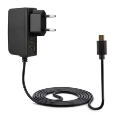 5V Power Supply
|
~€9 |
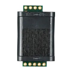 Sunlight CO2 Sensor
|
~€55 |
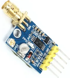 NEO-6M GPS Module (necessary for offline use of the device)
|
~€17 |
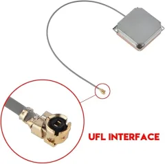 GPS Antenna 28dB High Gain (necessary for offline use of the device)
|
~€14 |
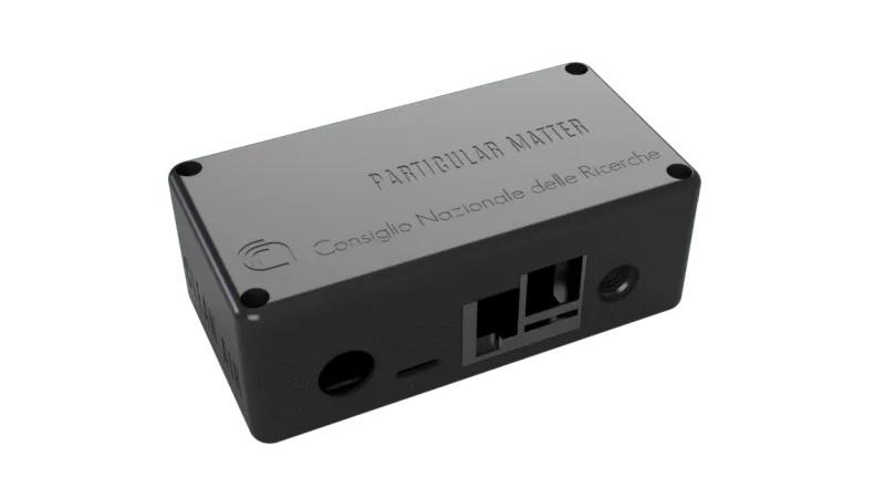
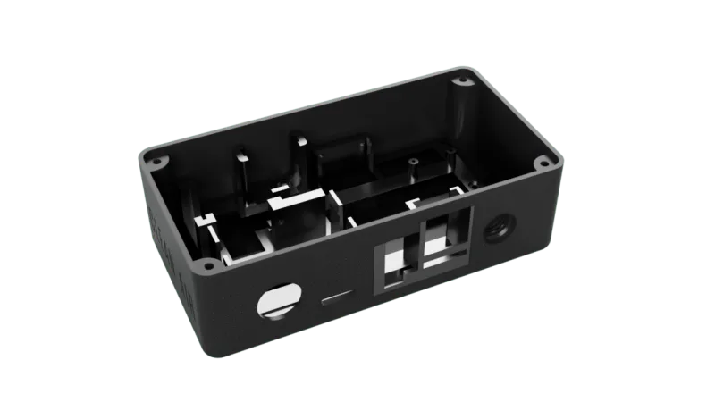
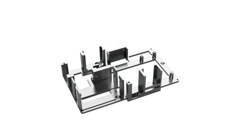
3D Printed Enclosure
Download the STL files for the 3D-printable enclosure:
Wiring Diagram
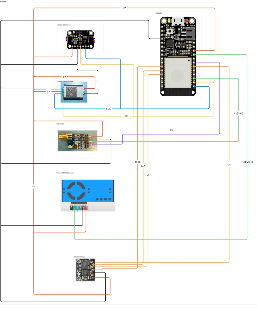
The HUZZAH32 (ESP32) is the central board: the BME280 and CO2 sensor share an I2C bus, the GPS and PM2.5 sensor each use a UART pair, and the SD card uses SPI. All modules share the same 5V and GND rails. Click the diagram to zoom in on the exact pin connections.
Assembly Instructions
-
1Wire the BME280 sensor (I2C) VIN to 5V, GND to GND, SCK to GPIO14 (SCL), SDI to the SDA pin
-
2Wire the Senseair Sunlight CO2 sensor (I2C, shares the bus with the BME280) 5V to 5V, GND to GND, SCL to GPIO14, SDA to the SDA pin
-
3Wire the NEO-6M GPS module (UART) VCC to 5V, GND to GND, TXD to GPIO13, RXD to GPIO27
-
4Wire the PMS5003 PM2.5 sensor (UART) VCC to 5V, GND to GND, TX to GPIO32 (RX is unused)
-
5Wire the SD card (SPI) VIN to 5V, GND to GND, CS to GPIO33, SCK to SCK, MOSI (MO) to MO, MISO to A5
-
6Double-check every connection against the wiring diagram Confirm the I2C, UART, SPI, and power rails all match before applying power
-
7Place components in the 3D printed enclosure Ensure proper airflow for the PM sensor and avoid blocking sensor vents
-
8Secure all connections and close the enclosure Use screws or clips to secure the enclosure lid
Important Notes
Double-check all wiring before powering on to avoid damaging components. ESP32 requires a stable 5V/1A power supply for reliable operation. The PMS5003 sensor needs proper ventilation — do not block air intake or exhaust.
Firmware Installation
Install the pre-built firmware using your web browser. No software installation required — the process uses WebUSB technology supported by Chrome, Edge, and Opera.
Download Firmware
Browse to the firmware folder on GitHub and download the latest .bin file:
Connect Device
Connect your ESP32 to your computer via USB cable and click “CONNECT” in the web interface.
Select your device from the popup dialog (usually shows as “USB Serial” or “CP210x”)
Install Firmware
Click “INSTALL” and select the firmware.bin file you downloaded in step 1.
The flashing process takes approximately 1–2 minutes. Do not disconnect during this process.
Verify Installation
Once complete, the device will restart. You should see a new WiFi network appear:
ESP32_Setup
Browser Compatibility
This method requires a browser with WebUSB support (Chrome, Edge, Opera). If you’re using Firefox or Safari, please switch to a compatible browser for firmware installation.
Device Registration
Configure your device to connect to your WiFi network and pair it with the ParticularMatter backend.
Quick Start
First Power-On
On boot, the device broadcasts a WiFi hotspot:
ESP32_Setup
12345678
Connect to the Captive Portal
Connect your phone or computer to the hotspot above. The setup page should appear automatically. If it doesn’t, open a browser and go to:
Enter Your Home WiFi
Select your WiFi network, enter the password, and save.
The device reboots, connects to your home network, and keeps the ESP32_Setup hotspot running for future access — you can return to it at any time to change settings.
Generate a One-Time Key
Need a one-time key? Log in to your dashboard and generate one:
- Go to dashboard.particularmatter.org
- Navigate to “Locations” → Select or create a location
- Click “Add Node” and then “Get Registration Code”
- Copy the generated code (valid for 24 hours)
Each registration code can only be used once and expires after 24 hours.
Pair with the Backend
Go to the device’s Node settings page — reachable at 192.168.4.1 while connected to the ESP32_Setup hotspot, or at its address on your home network — enter the one-time key from Step 4, and complete pairing.
Pairing Successful
Once paired, the device receives its Node ID and begins MQTT publishing. Your sensor will appear in your dashboard within 1–2 minutes and begin reporting data.
Dashboard Configuration
Once your device is registered, you can manage it through the web dashboard.
View Real-Time Data
Navigate to your location page to see live sensor readings displayed on interactive charts.
Manage Nodes
Add nodes to your locations, select sensor types, and mark whether they are indoor or outdoor.
Historical Data
View historical data with customizable time ranges from 10 minutes to 1 week.
Map View
See all your sensors on an interactive map. Mark locations as public to share data with the community.
Troubleshooting
Device Not Appearing in WiFi List
- Wait 1–2 minutes after powering on for the access point to start
- Ensure the device is powered with a stable 5V power supply
- Try resetting the device by unplugging and replugging power
- Check that firmware was installed correctly
Registration Fails
- Verify the one-time key was copied correctly (no extra spaces)
- Confirm the key hasn’t already been used — each one is single-use
- Ensure the registration code hasn’t expired (24-hour validity)
- Confirm the device has internet connectivity
No Data Appearing in Dashboard
- Wait 2–3 minutes after registration for first data to appear
- Check device logs in the configuration portal for errors
- Verify sensors are properly connected (check wiring)
- Ensure device has stable WiFi connection
WiFi Connection Drops Frequently
- Ensure you’re using a 2.4 GHz network (ESP32 doesn’t support 5 GHz)
- Move the device closer to your WiFi router
- Check for WiFi interference from other devices
- Consider using a WiFi repeater or mesh network
Sensor Readings Seem Incorrect
- Allow 24–48 hours for sensors to stabilize after first power-on
- Ensure proper airflow around the PM sensor (not blocked)
- Check sensor calibration values in dashboard settings
- Compare with nearby reference stations for validation
Still Having Issues?
If you’re still experiencing problems after following this guide:
Get help or report an issue on GitHub →